Electrical Transformer
TRANSFORMER
TRANSFORMER
Transformer is a static device where electrical Energy is transfer from one Electrical Circuit to totally disconnected another Electrical Circuit without changing of frequency.
Classification of Transformer:
1) Based on Construction
a) Shell type b) Core type c) Berry type
2) Based on the output voltage
a) Step up transformer b) Step down transformer
3) Based on the application
a) Power Transformer b) Distribution transformer
4) Based on the method of Colling
a) ONAN Cooling of Transformer b) ONAF Cooling of Transformer c) OFAF Cooling of Transformer d) OFWF Cooling of Transformer e) ODAF Cooling of Transformer f) ODWF Cooling of Transformer
5) Based on the number of windings
a) Two winding/Three winding etc. transformer
b) Single winding transformer or autotransformer
Classification Of Transformer(Briefly Discussion ):
1) Based on Construction
a) Shell Type:

The shape of this transformer is rectangular and it includes three essential parts like one core and two windings which are shown in the following figure. It has two windings namely primary and secondary. The arrangement of these windings can be done in one limb.
b) Core type:
In core type transformer both the primary and the secondary windings are placed on the side limbs whereas, in shell type transformer, the windings are placed on the central limbs of the transformer. The core type transformer has two magnetic circuits whereas the shell type transformer has one magnetic circuit.
c) Berry type
It is actually a shell type transformer but the name is related to the designer and its cylindrical shape. Berry type transformer has more than two independent magnetic circuits i.e. it has distributed magnetic circuits. The core construction of berry type transformer is like spokes of a wheal.
2) Based on the output voltage
a) Step up transformer
Step-up Transformer. A transformer in which the output (secondary) voltage is greater than its input (primary) voltage is called a step-up transformer. The step-up transformer decreases the output current for keeping the input and output power of the system equal.
b) Step down transformer
3) Based on the application
b) Distribution transformer
4) Based on the method of Colling
a) ONAN Cooling of Transformer
This is the simplest transformer cooling system. The full form of ONAN is “Oil Natural Air Natural”. Here natural convectional flow of hot oil is utilized for cooling. In convectional circulation of oil, the hot oil flows to the upper portion of the transformer tank and the vacant place is occupied by cold oil. This hot oil which comes to upper side, will dissipate heat in the atmosphere by natural conduction, convection and radiation in air and will become cold. In this way the oil in the transformer tank continually circulate when the transformer put into load.
As the rate of dissipation of heat in air depends upon dissipating surface of the oil tank, it is essential to increase the effective surface area of the tank. So additional dissipating surface in the form of tubes or radiators connected to the transformer tank. This is known as radiator of transformer or radiator bank of transformer. We have shown below a simplest form on natural cooling or ONAN cooling arrangement of an earthing transformer below.
b) ONAF Cooling of Transformer
c) OFAF Cooling of Transformer
d) OFWF Cooling of Transformer
e) ODAF Cooling of Transformer
f) ODWF Cooling of Transformer
5) Based on the number of windings
a) Two winding/Three winding etc. transformer
b) Single winding transformer or autotransformer
Advantages of Transformers
The advantages are mentioned below:
- Its foremost advantage is controlling and stabilizing the voltage transmission.
- It does not require any starting time.
- It is highly efficient with less capital investment and low maintenance.
- They provide isolation to the ground.
- There are no moving parts in Transformers.
Disadvantages of Transformer
There are some drawbacks in the performance of Transformers. Some of them are mentioned below.
- Due to its material in the making of the iron core, there is wastage in the current flow.
- It gives out lot of heat which requires cooling. This creates a break in the flow of the current.
Applications of Transformers
Some of the applications are listed below:
- Due to the feature of equal transmission and distribution of electrical power, the Transformers are used in power plants, industrial plants and the traditional electric utility companies.
- They are used for the purpose of controlling heavy power supply.
- They are used as step up/down devices in power transmission.
EMF Equation Of The Transformer
Let,N1 = Number of turns in primary winding
N2 = Number of turns in secondary winding
Φm = Maximum flux in the core (in Wb) = (Bm x A)
f = frequency of the AC supply (in Hz)

As, shown in the fig., the flux rises sinusoidal to its maximum value Φm from 0. It reaches to the maximum value in one quarter of the cycle i.e. in T/4 sec (where, T is time period of the sin wave of the supply = 1/f).
Therefore,
average rate of change of flux = Φm /(T/4) = Φm /(1/4f)
Therefore,
average rate of change of flux = 4f Φm ....... (Wb/s).
Now,
Induced emf per turn = rate of change of flux per turn
Therefore, average emf per turn = 4f Φm ..........(Volts).
Now, we know, Form factor = RMS value / average value
Therefore, RMS value of emf per turn = Form factor X average emf per turn.
As, the flux Φ varies sinusoidally, form factor of a sine wave is 1.11
Therefore, RMS value of emf per turn = 1.11 x 4f Φm = 4.44f Φm.
RMS value of induced emf in whole primary winding (E1) = RMS value of emf per turn X Number of turns in primary winding
E1 = 4.44f N1 Φm ............................. eq 1
Similarly, RMS induced emf in secondary winding (E2) can be given as
E2 = 4.44f N2 Φm. ............................ eq 2
from the above equations 1 and 2,

For an ideal transformer on no load, E1 = V1 and E2 = V2 .
where, V1 = supply voltage of primary winding
V2 = terminal voltage of secondary winding
Voltage Transformation Ratio (K)
As derived above,
This constant K is known as voltage transformation ratio.
- If N2 > N1, i.e. K > 1, then the transformer is called step-up transformer.
- If N2 < N1, i.e. K < 1, then the transformer is called step-down transformer.
Types of Losses in a Transformer
There are different kinds of losses that will be occurred in the transformer such as iron, copper, hysteresis, eddy, stray & dielectric. The copper loss mainly occurs due to the resistance in the transformer winding whereas hysteresis losses will be occurred due to the magnetization change within the core.
a) Iron Losses in a Transformer
Iron losses mainly occur through the alternating flux within the transformer’s core. Once this loss occurs within the core then it is called core loss. This kind of loss mainly depends on the material’s magnetic properties within the core of the transformer. The core in the transformer can be made with iron, so these are called iron losses. This type of loss can be categorized into two types like hysteresis as well as eddy current.
b) Hysteresis Loss
This kind of loss mainly occurs when the alternating current is applied to the core of the transformer then the magnetic field will be reversed. This loss mainly depends on the core material used in the transformer. To reduce this loss, the high-grade core material can be used. CRGO- Cold rolled grain oriented Si steel can be used commonly like the core of the transformer so that Hysteresis loss can be reduced.
Magnetic Hysteresis Loop

The Magnetic Hysteresis loop above, shows the behavior of a ferromagnetic core graphically as the relationship between B and H is non-linear. Starting with an unmagnetized core both B and H will be at zero, point 0 on the magnetization curve.
If the magnetization current, i is increased in a positive direction to some value the magnetic field strength H increases linearly with i and the flux density B will also increase as shown by the curve from point 0 to point a as it heads towards saturation.
Now if the magnetizing current in the coil is reduced to zero, the magnetic field circulating around the core also reduces to zero. However, the coils magnetic flux will not reach zero due to the residual magnetism present within the core and this is shown on the curve from point a to point b.
To reduce the flux density at point b to zero we need to reverse the current flowing through the coil. The magnetizing force which must be applied to null the residual flux density is called a “Coercive Force”. This coercive force reverses the magnetic field re-arranging the molecular magnets until the core becomes unmagnetized at point c.
An increase in this reverse current causes the core to be magnetized in the opposite direction and increasing this magnetization current further will cause the core to reach its saturation point but in the opposite direction, point d on the curve.
This point is symmetrical to point b. If the magnetizing current is reduced again to zero the residual magnetism present in the core will be equal to the previous value but in reverse at point e.
Again reversing the magnetizing current flowing through the coil this time into a positive direction will cause the magnetic flux to reach zero, point f on the curve and as before increasing the magnetization current further in a positive direction will cause the core to reach saturation at point a.
Then the B-H curve follows the path of a-b-c-d-e-f-a as the magnetizing current flowing through the coil alternates between a positive and negative value such as the cycle of an AC voltage. This path is called a Magnetic Hysteresis Loop.
The effect of magnetic hysteresis shows that the magnetization process of a ferromagnetic core and therefore the flux density depends on which part of the curve the ferromagnetic core is magnetized on as this depends upon the circuits past history giving the core a form of “memory”. Then ferromagnetic materials have memory because they remain magnetized after the external magnetic field has been removed.
However, soft ferromagnetic materials such as iron or silicon steel have very narrow magnetic hysteresis loops resulting in very small amounts of residual magnetism making them ideal for use in relays, solenoids and transformers as they can be easily magnetized and demagnetized.
Since a coercive force must be applied to overcome this residual magnetism, work must be done in closing the hysteresis loop with the energy being used being dissipated as heat in the magnetic material. This heat is known as hysteresis loss, the amount of loss depends on the material’s value of coercive force.
By adding additive’s to the iron metal such as silicon, materials with a very small coercive force can be made that have a very narrow hysteresis loop. Materials with narrow hysteresis loops are easily magnetized and demagnetized and known as soft magnetic materials.
c) Eddy Current Loss
Once the flux is connected to a closed circuit, then an e.m.f can be induced within the circuit and there is a supply in the circuit. The flow of current value mainly depends on the sum of an e.m.f and resistance in the region of the circuit.
The core of the transformer can be designed with a conducting material. The flow of current in the emf can be supplied within the body of the material. This flow of current is known as eddy current. This current will occur once the conductor experiences an altering magnetic field.
When these currents are not accountable for doing any functional task, then it generates a loss within the magnetic material. So it is called as an Eddy Current Loss. This loss can be reduced by designing the core using slight laminations.
d) Copper Loss
Copper losses occur because of the Ohmic resistance in the windings of the transformer. If the primary and secondary windings of the transformer are I1 and I2, then the resistance of these windings is R1 & R2. So the copper losses that occurred in the windings are I12R1 & I22R2 respectively. So, the entire copper loss will be
Pc = I12R1 + I22R2
These losses also called variable or ohmic losses because these losses will change based on the load.
e) Stray Loss
These types of losses in a transformer can be occurred because of the occurrence of the leakage field. As compared with copper and iron losses, the percentage of stray losses are less, so these losses can be neglected.
f) Dielectric Loss
This loss mainly occurs within the oil of the transformer. Here oil is an insulating material. Once the oil in the transformer gets deteriorates otherwise when oil quality diminishes then the transformer’s efficiency will be affected.
The Phasor Diagram Of Transformer:
a) Transformer at on No Load Condition
When the transformer is operating at no load, the secondary winding is open-circuited, which means there is no load on the secondary side of the transformer and, therefore, current in the secondary will be zero. While primary winding carries a small current I0 called no-load current which is 2 to 10% of the rated current.
This current is responsible for supplying the iron losses (hysteresis and eddy current losses) in the core and a very small amount of copper losses in the primary winding. The angle of lag depends upon the losses in the transformer. The power factor is very low and varies from 0.1 to 0.15.
The no-load current consists of two components:
- Reactive or magnetizing component Im
(It is in quadrature with the applied voltage V1. It produces flux in the core and does not consume any power).
- Active or power component Iw, also know as a working component
(It is in phase with the applied voltage V1. It supplies the iron losses and a small amount of primary copper loss).
The following steps are given below to draw the phasor diagram:
- The function of the magnetizing component is to produce the magnetizing flux, and thus, it will be in phase with the flux.
- Induced emf in the primary and the secondary winding lags the flux ϕ by 90 degrees.
- The primary copper loss is neglected, and secondary current losses are zero as
Is = 0.
Therefore, the current I0 lags behind the voltage vector V1 by an angle ϕ0 called the no-load power factor angle and is shown in the phasor diagram above. - The applied voltage V1 is drawn equal and opposite to the induced emf E1 because the difference between the two, at no load, is negligible.
- Active component Iw is drawn in phase with the applied voltage V1.
- The phasor sum of magnetizing current Im and the working current Iw gives the no-load current I0.

From the phasor diagram drawn above, the following conclusions are made: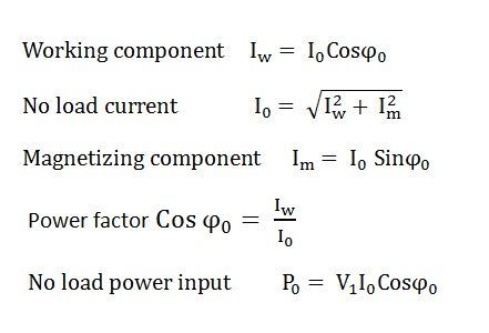
b) Transformer at ON load condition
Now we will examine the behavior of the above-said transformer on load, which means the load is connected to the secondary terminals. Consider, a transformer having core loss but no copper loss and leakage reactance. Whenever a load is connected to the secondary winding, the load current will start to flow through the load as well as the secondary winding.
This load current solely depends upon the characteristics of the load and also upon the secondary voltage of the transformer. This current is called secondary current or load current, here it is denoted as I2. As I2 is flowing through the secondary, a self MMF in secondary winding will be produced. Here it is N2I2, where, N2 is the number of turns of the secondary winding of the transformer.
This MMF or magnetomotive force in the secondary winding produces flux φ2. This φ2 will oppose the main magnetizing flux and momentarily weakens the main flux and tries to reduce primary self-induced emf E1. If E1 falls below the primary source voltage V1, there will be an extra current flowing from source to primary winding.
This extra primary current I2′ produces extra flux φ′ in the core which will neutralize the secondary counter flux φ2. Hence the main magnetizing flux of core, Φ remains unchanged irrespective of load. So total current, this transformer draws from the source can be divided into two components.
The first one is utilized for magnetizing the core and compensating the core loss, i.e., Io. It is the no-load component of the primary current. The second one is utilized for compensating the counter flux of the secondary winding. It is known as the load component of the primary current. Hence total no-load primary current I1 of an electrical power transformer having no winding resistance and leakage reactance can be represented as follows
Where θ2 is the angle between the Secondary Voltage and Secondary Current of the transformer.
Now we will proceed one further step toward a more practical aspect of a transformer.
c) Transformer at NO Load condition (with resistive windings but No leakage reactance)
Now, consider the winding resistance of the transformer but no leakage reactance. So far we have discussed the transformer which has ideal windings, means winding with no resistance and leakage reactance, but now we will consider one transformer which has internal resistance in the winding but no leakage reactance. As the windings are resistive, there would be a voltage drop in the windings.
We have proved earlier that, total primary current from the source on load is I1. The voltage drop in the primary winding with resistance, R1 is R1I1. Obviously, induced emf across primary winding E1, is not exactly equal to source voltage V1. E1 is less than V1 by voltage drop I1R1.
Again in the case of secondary, the voltage induced across the secondary winding, E2 does not totally appear across the load since it also drops by an amount I2R2, where R2 is the secondary winding resistance and I2 is secondary current or load current.
Similarly, the voltage equation of the secondary side of the transformer will be:

d) Transformer at NO Load condition (with resistive windings and No leakage reactance)
Now we will consider the condition when there is leakage reactance of the transformer as well as winding resistance of the transformer.
Let leakage reactances of primary and secondary windings of the transformer are X1 and X2 respectively. Hence total impedance of primary and secondary winding of transformer with resistance R1 and R2 respectively can be represented as,
We have already established the voltage equation of a transformer on load, with only resistances in the windings, where voltage drops in the windings occur only due to resistive voltage drop.
But when we consider leakage reactance of transformer windings, the voltage drop occurs in the winding not only due to resistance but also due to the impedance of transformer windings. Hence, the actual voltage equation of a transformer can easily be determined by replacing resistances R1 & R2 in the previously established voltage equations with Z1 and Z2.
Therefore, the voltage equations are,
Resistance drops are in the direction of the current vector. But a reactive drop will be perpendicular to the current vector as shown in the above vector diagram of the transformer.
Equivalent circuit of Single Phase Transformer
Equivalent Circuit Diagram Of A Transformer Is Basically A Diagram Which Can Be Resolved Into An Equivalent Circuit In Which The Resistance And Leakage Reactance Of The Transformer Are Imagined To Be External To The Winding.
The Equivalent Circuit Diagram Of Transformer Is Given Below:-
Equivalent Circuit Diagram Of A Transformer Is Basically A Diagram Which Can Be Resolved Into An Equivalent Circuit In Which The Resistance And Leakage Reactance Of The Transformer Are Imagined To Be External To The Winding.
The Equivalent Circuit Diagram Of Transformer Is Given Below:-
Where,
R1 = Primary Winding Resistance.
R2= Secondary Winding Resistance.
I0= No-Load Current.
Iµ = Magnetizing Component,
Iw = Working Component,
This Iµ & Iw Are Connected In Parallel Across The Primary Circuit. The Value Of E1 ( Primary E.M.F ) Is Obtained By Subtracting Vectorially I1 Z1 From V1 . The Value Of X0 = E1 / I0 And R0 = E1 /Iw. We Know That The Relation Of E1 And E2 Is E2 /E1 = N2 /N1 = K , ( Transformation Ratio )
From The Equivalent Circuit , We Can Easily Calculate The Total Impedance Of To Transfer Voltage, Current, And Impedance Either To The Primary Or The Secondary.
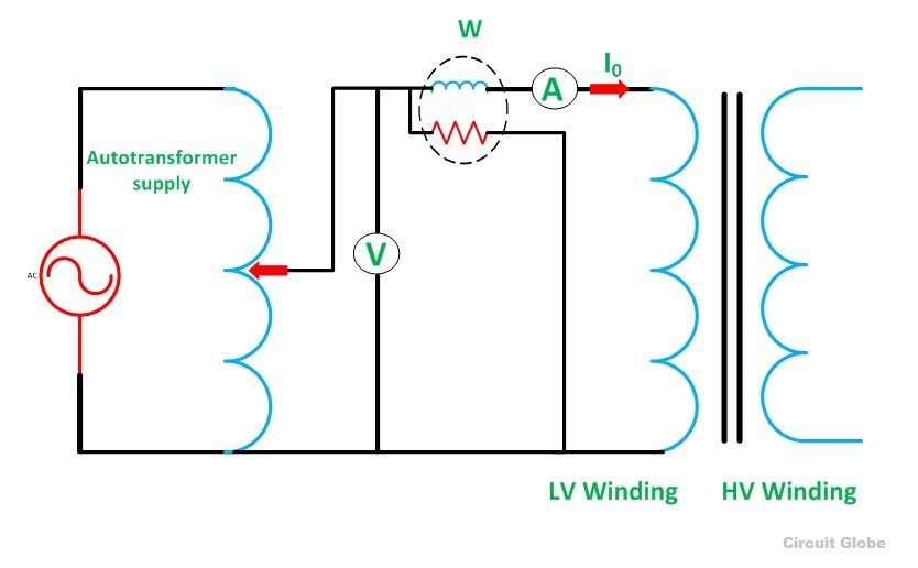
Open Circuit Test And Short Circuit Test On Transformer :
Open Circuit Test
The purpose of the open-circuit test is to determine the no-load current and losses of the transformer because of which their no-load parameters are determined. This test is performed on the primary winding of the transformer. The wattmeter, ammeter and the voltage are connected to their primary winding. The nominal rated voltage is supplied to their primary winding with the help of the ac source.

The secondary winding of the transformer is kept open, and the voltmeter is connected to their terminal. This voltmeter measures the secondary induced voltage. As the secondary of the transformer is open, thus no-load current flows through the primary winding.
The value of no-load current is very small as compared to the full rated current. The copper loss occurs only on the primary winding of the transformer because the secondary winding is open. The reading of the wattmeter only represents the core and iron losses. The core loss of the transformer is the same for all types of loads.
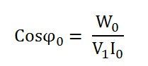
Calculation of open-circuit test
Let,
- W0 – wattmeter reading
- V1 – voltmeter reading
- I0 – ammeter reading
Then the iron loss of the transformer Pi = W0 and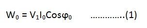
The no-load power factor is
Working component Iw is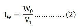
Putting the value of W0 from the equation (1) in equation (2) you will get the value of the working component as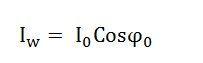
Magnetizing component is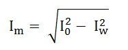
No-load parameters are given below:
Equivalent exciting resistance is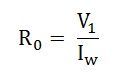
Equivalent exciting reactance is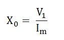
The phasor diagram of the transformer at no load or when an open circuit test is performed is shown below

The iron losses measured by the open circuit test is used for calculating the efficiency of the transformer.
Short Circuit Test
The short circuit test is performed for determining the below mention parameter of the transformer.
- It determines the copper loss occur on the full load. The copper loss is used for finding the efficiency of the transformer.
- The equivalent resistance, impedance, and leakage reactance are known by the short circuit test.
The short circuit test is performed on the secondary or high voltage winding of the transformer. The measuring instrument like wattmeter, voltmeter and ammeter are connected to the high voltage winding of the transformer. Their primary winding is short-circuited by the help of thick strip or ammeter which is connected to its terminal.
The low voltage source is connected across the secondary winding because of which the full load current flows from both the secondary and the primary winding of the transformer. The full load current is measured by the ammeter connected across their secondary winding.
The circuit diagram of the short circuit test is shown below:
The low voltage source is applied across the secondary winding, which is approximately 5 to 10% of the normal rated voltage. The flux is set up in the core of the transformer. The magnitude of the flux is small as compared to the normal flux.
The iron loss of the transformer depends on the flux. It is less occur in the short circuit test because of the low value of flux. The reading of the wattmeter only determines the copper loss occurred, in their windings. The voltmeter measures the voltage applied to their high voltage winding. The secondary current induces in the transformer because of the applied voltage.
Calculation of Short Circuit Test
Let,
- Wc – Wattmeter reading
- V2sc – voltmeter reading
- I2sc – ammeter reading
Then the full load copper loss of the transformer is given by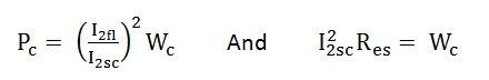
Equivalent resistance referred to the secondary side is
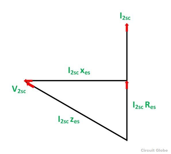
The phasor diagram of the short circuit test of the transformer is shown below

From the phasor diagram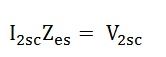
Equivalent impedance referred to the secondary side is given by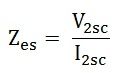
The equivalent reactance referred to the secondary side is given by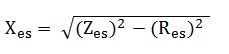
The voltage regulation of the transformer can be determined at any load and power factor after knowing the values of Zes and Res.
In the short circuit test the wattmeter record, the total losses, including core loss but the value of core loss are very small as compared to copper loss so the core loss can be neglected.
Properties Of Ideal Transformer
i) Winding Resistance is negligible.
Phasor Diagram Of An Ideal Transformer
Given figure shows the phasor diagram of an ideal transformer.

Since,
Here ,V1 = Primary Supply Voltage.
E1 = Primary Induced Emf.
I1 = Primary Current.
Ø = Mutual flux.
V2 = Secondary Output Voltage.
E2 = Secondary Induced Emf.
Efficiency of Transformer
The definition of efficiency is similar to an electrical machine. It is the ratio of output power and input power. The efficiency can be calculated by the following formula.
Efficiency = Output Power / Input Power.
The transformer is a highly efficient device and the load efficiency of these devices mainly ranges between 95% – 98.5%. When a transformer is highly efficient, then its input and output have almost the same value, and therefore it is not practical to calculate the efficiency of the transformer by using the above formula. But to find its efficiency, the following formula is better to use
Efficiency = (Input – Losses) / Input => 1 – (Losses /Iinput).
Let copper loss is I2R1 whereas iron loss is Wi
Efficiency = 1-Losses/Input
= 1-I12R1+Wi/V1I1CosΦ1
Ƞ = 1-(I1R1/V1CosΦ1) –Wi/ V1I1CosΦ1
Differentiate the above equation with respect to ‘I1’
d Ƞ/dI1= 0- (R1/V1CosΦ1) + Wi/V1I12 CosΦ1
‘Ƞ’ is maximum at d Ƞ/dI1 =0
Therefore, efficiency ‘Ƞ’ will be maximum at
R1/V1CosΦ1 = Wi/V1I12 CosΦ1
I12R1/ V1I12 CosΦ1 = Wi/V1I12 CosΦ1
I12R1 = Wi
Therefore, the transformer efficiency can be highest when iron and copper losses are equal.
So, Copper loss = Iron loss.
Thus, this is all about an overview of the types of losses in a transformer. In a transformer, energy loss can be occurred due to several reasons. So the transformer efficiency will be reduced. The main reasons for different types of losses in a transformer are due to the effect of heat in the coil, magnetic flux leakage, magnetization & demagnetization of the core.
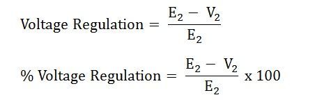
Voltage Regulation of a Transformer
Definition: The voltage regulation is defined as the change in the magnitude of receiving and sending voltage of the transformer. The voltage regulation determines the ability of the transformer to provide the constant voltage for variable loads.
When the transformer is loaded with continuous supply voltage, the terminal voltage of the transformer varies. The variation of voltage depends on the load and its power factor.
Mathematically, the voltage regulation is represented as:
 where,
E2 – secondary terminal voltage at no load
V2 – secondary terminal voltage at full load
The voltage regulation by considering the primary terminal voltage of the transformer is expressed as,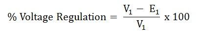 Let us understand the voltage regulation by taking an example explained below:
If the secondary terminals of the transformer are open-circuited or no load is connected to the secondary terminals, the no-load current flows through it.
If the no current flows through the secondary terminals of the transformer, the voltage drops across their resistive and reactive load become zero. The voltage drop across the primary side of the transformer is negligible.
If the transformer is fully loaded, i.e., the load is connected to their secondary terminal, the voltage drops appear across it. The value of the voltage regulation should always be less for the better performance of the transformer.
From the circuit diagram shown above, the following conclusions are made
- The primary voltage of the transformer is always greater than the induced emf on the primary side. V1>E1
- The secondary terminal voltage at no load is always greater than the voltage at full load condition. E2>V2
By considering the above circuit diagram, the following equations are drawn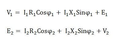 The approximate expression for the no-load secondary voltage for the different types of the load is
1. For inductive load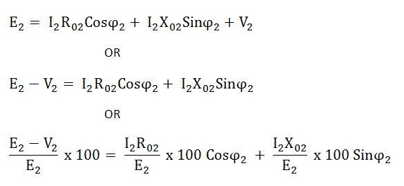 Where,
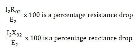
2. For Capacitive load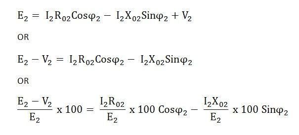
Parallel operations of transformers:
When we connect the primary windings of two transformers to a common supply voltage and the secondary windings of both the transformers to a common load, this type of connection of transformer is said to be the parallel operation of transformers.
Reasons for parallel operation
The reasons for operating the transformers in parallel are as follows:
- This is an economical method because a single large transformer is uneconomical for large load.
- If the transformers are connected in parallel, we require extra load then we can expand the system by adding more transformers in the future.
- Parallel operation reduces the space capacity of the substation when we connect transformers of standard size.
- The parallel connection maximizes the electrical power system availability as we can shut down any system for maintenance without affecting other systems performance.
Single-phase transformers in parallel
The diagram drawn below shows the circuit diagram of two transformers A and B connected in parallel.
Let,
a1 = turns ratio of transformer A
a2 = turns ratio of transformer B
ZA = equivalent impedance of transformer A referred to the secondary side.
ZB = equivalent impedance of transformer B referred to the secondary side.
ZL = load impedance across the secondary side.
IA = current supplied to the load by the secondary of transformer A.
IB = current supplied to the load by the secondary of transformer B.
VL= load secondary voltage.
IL= load current
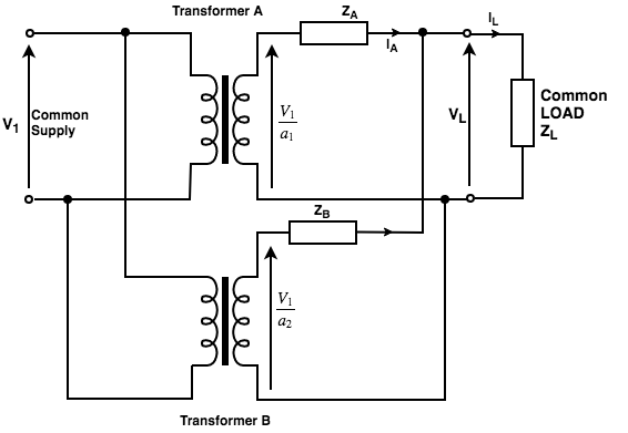
Fig: Two single-phase transformers in parallel.
By KCL,
IA+IB=IL
BY KVL,
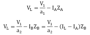
By solving the above two equations, we get
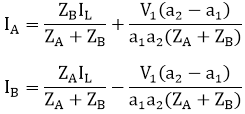
Each of these currents has two components; the first component represents the transformer's share of the load current and the second component is a circulating current in the secondary windings.
Circulating currents have the following undesirable effects:
- They increase the copper loss.
- They overload one transformer and reduce the permissible load KVA.
Conditions for parallel operation of Single-Phase transformers
Necessary conditions
- The transformers must have the same polarities.
- The transformers should have equal turn ratios.
Desirable conditions
- The voltages at full load across transformers internal impedance should be equal.
- The ratios of their winding resistances to reactance should be equal for both transformers. This condition ensures that both transformers operate at the same power factor, thus sharing active power and reactive voltamperes according to their ratings.
Three-phase transformers in parallel
The conditions for proper parallel operation of single-phase transformers are as follows:
- The polarities of the transformers should be the same.
- Identical primary and secondary voltage ratings.
- Impedances inversely proportional to the kVA ratings.
- Identical X/R ratios in the transformer impedances.
The condition for the parallel operation of single phase and three phase transformer is the same but with the following additions:
- The phase sequence of the transformers must be identical.
- The primary and secondary voltages of all the transformers connected in parallel must have the same phase shift.
In an auto transformer, one single winding is used as primary winding as well as secondary winding. But in two windings transformer two different windings are used for primary and secondary purpose. A circuit diagram of auto transformer is shown below.

The winding AB of total turns N1 is considered as primary winding. This winding is tapped from point ′C′ and the portion BC is considered as secondary. Let’s assume the number of turns in between points ′B′ and ′C′ is N2.
If V1 voltage is applied across the winding i.e. in between ′A′ and ′C′.![]()
Hence, the voltage across the portion BC of the winding, will be,![]()
As BC portion of the winding is considered as secondary, it can easily be understood that value of constant ′k′ is nothing but turns ratio or voltage ratio of that auto transformer. When load is connected between secondary terminals i.e. between ′B′ and ′C′, load current I2 starts flowing. The current in the secondary winding or common winding is the difference of I2 and I1.
Advantages of using Auto Transformers
The advantages of an auto transformer include:
- For transformation ratio = 2, the size of the auto transformer would be approximately 50% of the corresponding size of two winding transformer. For transformation ratio say 20 however the size would be 95 %. The saving in cost of the material is of course not in the same proportion. The saving of cost is appreciable when the ratio of transformer is low, that is lower than 2. Thus auto transformer is smaller in size and cheaper.
- An auto transformer has higher efficiency than two winding transformer. This is because of less ohmic loss and core loss due to reduction of transformer material.
- Auto transformer has better voltage regulation as voltage drop in resistance and reactance of the single winding is less.
Disadvantages of Using Auto Transformer
The disadvantages of an auto transformer include:
- Because of electrical conductivity of the primary and secondary windings the lower voltage circuit is liable to be impressed upon by higher voltage. To avoid breakdown in the lower voltage circuit, it becomes necessary to design the low voltage circuit to withstand higher voltage.
- The leakage flux between the primary and secondary windings is small and hence the impedance is low. This results into severer short circuit currents under fault conditions.
- The connections on primary and secondary sides have necessarily needs to be same, except when using interconnected starring connections. This introduces complications due to changing primary and secondary phase angle particularly in the case of delta/delta connection.
- Because of common neutral in a star/star connected auto transformer it is not possible to earth neutral of one side only. Both their sides should have their neutrality either earth or isolated.
- It is more difficult to maintain the electromagnetic balance of the winding when voltage adjustment toppings are provided. It should be known that the provision of tapping on an auto transformer increases considerably the frame size of the transformer. If the range of tapping is very large, the advantages gained in initial cost is lost to a great event.
Applications of Auto Transformers
The applications of an auto transformer include:
- Compensating voltage drops by boosting supply voltage in distribution systems.
- Auto transformers with a number of tapping are used for starting induction and synchronous motors.
- Auto transformer is used as variac in laboratory or where continuous variable over broad ranges are required.
Comments
Post a Comment